Integrating AutoCAD into ArcGIS
Problem: The facilities management at North Carolina State University (NCSU) has asked you to georeference a CAD file containing a drawing of all the features on campus, and to create a geodatabase that includes the buildings and other campus features that they will use for planning and maintenance purposes.
Analysis Procedures:
Strategies and Methods: NCSU’s facilities management has provided a CAD file and an orthophoto of campus. I used ArcGIS (ArcMap and ArcCatalog, versions 10.5.1) to perform the following procedures. I began by reviewing the attributes of the features in the CAD file and displaying only the features of interest. I set the appropriate coordinate system to the data frame so the CAD data file could be georeferenced to the provided orthophoto using the Georeferencing toolbar in ArcMap. I adjusted the scale of the CAD drawing and shifted the image so it was close to the orthophoto, and then I selected two control points to be used for the georeferencing: one on a bridge near the southeast extent of the file, and the other on the corner of a building in the northwest extent of the drawing. I updated the georeferencing and saved the results as a World file. I closed the polygons of any erroneously open features (polylines that should be polygons) using the Feature to Polygon tool. I created a file geodatabase and added feature datasets with the appropriate coordinate system. I used Select by Attributes to isolate the desired features from the CAD polyline layer and exported the data as a shapefile, and then I used the Feature Class to Feature Class tool to add these features to the appropriate feature dataset within the file geodatabase. However, the step of exporting the data as a shapefile is not required; the Feature Class to Feature Class tool could be used, with an SQL structured query to isolate the appropriate features, and directly add them to the feature dataset or file geodatabase (Fig. 1).
Workflow Diagram:

Fig. 1. Workflow diagram for integrating CAD data into ArcGIS.
Results: These procedures create properly georeferenced files that show the features that were created as a CAD drawing converted to a format that can be manipulated and analyzed using ArcGIS. The georeferenced files properly align with the features seen in an orthophoto of the same area (Fig. 2).
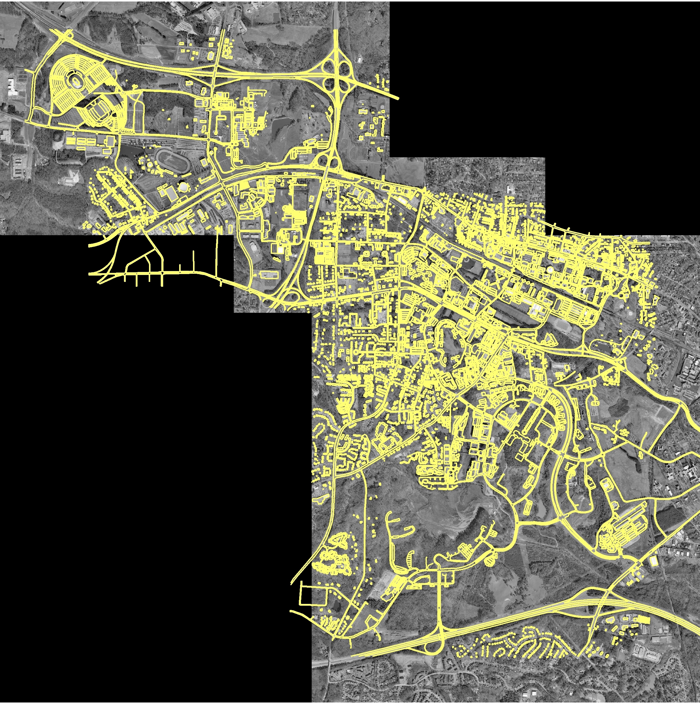 Fig. 2. The features of the CAD drawing (yellow) are laid over an orthophoto used to georeference the file. The image shows the alignment of the CAD features after they have been georeferenced. Click on image to open larger version.
Application and Reflection: CAD drawings are a common tool used by engineers for drafting and design. They offer the benefit of being stored electronically, but can be of even greater use if they can be properly placed in space. Georeferencing is a method that can tie a CAD drawing to its location.
Problem Description: A wetland needs to be created for mitigation purposes, and the and manager needs to study several proposed sites to determine the best placement for the created wetland.
Data needed: An orthophoto of the proposed areas could be obtained through EarthExplorer. Soils and slope data could be obtained from the local county GIS services. The environmental engineer on the project would create a CAD drawing.
Analysis Procedures: You would use the orthophoto to georeference the CAD drawing. You could adjust the drawing to fit the local landscape, and use the soils and slope data to examine how the proposed wetland would impact the area. This would allow you to determine which of the proposed locations would be best for the placement and creation of the wetland.
